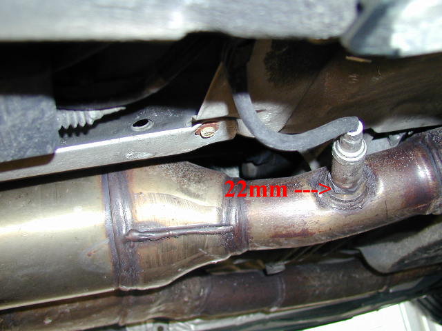
^Oxygen Sensor^
The 02 sensor measures the level of oxygen in the exhaust pipe and determines whether an engine is running lean or running rich from the readings that the sensor gets and sends to the ECU(electronic control unit). The voltage received from the 02 sensor determines whether the engine is running rich or running lean, the voltages received from the 02 sensor vary from 0-1volt. So when the ECU receives0-0.2 volts, this means that the engine is running lean as there is a high content of oxygen in the exhaust, this is because of low fuel levels being burnt so not all of the oxygen can burn so there is a high level of oxygen left over in the exhaust. So this low voltage tells the ECU to inject more fuel into the combustion chamber. When the voltage received by the ECU from the 02 sensor is around 0.3-0.6 volts this means the engine has reached stoichiometry and is running the perfect air/fuel ratio. When the ECU receives 0.7-1volt this means that the engine is running rich, this causes low oxygen content in the exhaust as most of it has been burnt due to the high level of fuel in the combustion chamber. This tells the ECU that less fuel is required and the ECU injects less fuel into the combustion chamber. When the engine is cruising at set RPM, the 02 sensor will cycle the air/fuel mixture rich and lean very quickly, this is known as closed loop and is designed to reduce harmful emissions.
COMPONENT LIST
The components required for this circuit are, 3 x 1N4001 diodes, 2 x 0.1uF(micro Farads) Capacitors, 1 x 10,000 ohm resistor and 6 x resistors which values have to calculated (this will be shown later on), 1 x 9v1(9.1volt) Zener Diode, 1 x Red LED, 1 x Yellow LED, 1 x Green LED and 1 x LM324 IC(Operational Amplifier)

CALCULATIONS
To calculate the correct resistor size across R2,R3 and R4, the first thing that needs to be done is to minus 0.6 volts from the power supply as the supply has to go through a diode so this would be 12v-0.6v=11.4volts, then 1.8 volts has to be minused from 11.4volts as this is the voltage required to push through the LED's. So this would make 11.4v-1.8v=9.6volts. Then you would divide 9.6 volts by the current required to turn on the LED's which is 9.5mA, this would be done using ohm's law which is R=V/I, so this would be 9.6v/0.0095A=1010 ohms, this is the answer for R2 and R4 but R3, has different value due to the diode before the yellow LED. So this would be 11.4 v-0.6v-1.8v= 9.0volts. This would mean that 9volts is divided by the current required which is, 9.0v/0.0095A=947 ohm's this is the resistor that is required for R3.
R5 would be 11.4 volts minused by 9.1 volts, as this is the voltage required to push through the Zener Diode, so this would be 11.4v-9.1v=2.3 volts. Then that voltage is divide by the current required which is 5.6mA, so this would be 2.3v/0.0056A=411 ohm's. The value for R6 has already been given so that is 10,000 ohm's, next the current had to calculated on the voltage divider circuit using ohm's law which is I=V/R. So since the voltage supply at the divider circuit is 9.1 volts(this is regulated using the Zener Diode), you would then minus 0.63 volts from supply voltage as this is the voltage required after the first resistor. So this would 9.1-0.63=8.47 volts, I=V/R, I=8.47v/10,000ohm's, so the current then equals 0.000847A.
This leaves just R7 and R8 to be worked out. So the resistances are worked out using ohm's law which is, R=V/I, so R7= 0.23 volts as this is the voltage required above R7 divided by the amperage which is 0.000847A. This means that R7=272 ohm's, and R8= 0.63-0.23=0.4 volts(this is the voltage drop) which is then divided by the current. R=V/I, R=0.4v/0.000847A= 472 ohm's.
This is how all the resistors are worked out for this circuit. The wiring diagram can be seen below as a reference to see what has been calculated.
EXPLANATION ON HOW CIRCUIT WORKS


This circuit works by using the 4 operational amplifiers (the IC chip) that each produce different outputs to light up the LED's, the first diode at the 12 volt power source is their to stop current flowing in the wrong direction going back towards the power source. Just before R5 there is a 11.4 volt input going to the chip to power it, this is going into pin 4, R5 is in place to create the 2.3volt, voltage drop in order to create the 9.1 volts of available voltage for the zener diode. This 9.1 volts is then the voltage supply for the voltage divider circuit. The first resistor in the circuit R6 is already been given to us(10,000 ohm's) and this is used to create a 8.47 volt, voltage drop so that there is 0.63 volts of available voltage at pin 5 on the op amp. Then R8 creates a 0.4 volt, voltage drop so that there is 0.23 volts of available voltage at pin 13. There is always a constant 11.4 volts going to the LED's after the first diode (D2). And the capacitors are in place to smooth the signals in the circuit.

The 02 sensor input is wired up to pins 12,9,6 and 3. And the op amps are used as comparitors, when the voltage signal from the 02 sensor is below 0.23 volts the output voltage from pin 14 is 0 volts, this grounds that part of the circuit and causes the green LED to light up. When the voltage exceeds 0.23 volts, then the positive side of the input for the comparitor is greater and the output for pin 14 will be 11.4 volts, this means there will be 11.4 volts on both sides of the green LED (LED6) and the LED will turn off as current cannot flow through the LED to switch it on. With the green LED this will show that the engine is running lean and the ECU will then inject more fuel to richen the mixture(this is when the engine is on closed loop)
With the voltage now being greater than 0.23 volts from the oxygen sensor, this causes the negative input voltage of the comparitor to be higher than the positive input and this causes a 0v output for pin 8 and this causes the yellow LED (LED 5) to switch on as this part of the circuit can now ground. The yellow LED will remain on until the voltage exceeds 0.63 volts. When the yellow LED switches on this shows that the air/fuel ratio has reached lambda or the correct air/fuel ratio of 14.7 parts or air to 1 part of fuel (14.7:1).
When the voltage exceeds 0.63 volts the Red LED (LED1) will switch on, this shows that the engine is running rich and the ECU will then inject less fuel into the combustion chamber (when the engine is on closed loop). The problem with this circuit is that when the Red LED comes on the yellow LED will remain on until the voltage falls below 0.23 volts. So to fix this problem there is an output from pin 1 that sends positive 10.8 volts to the negative side of the LED, so with positive 10.8 volts on the positive side of the diode no current can flow and the yellow LED switches off. And allows the red LED to remain on. The reason that the voltages are 10.8 volts, is that there is the initial voltage drop to get through the first diode of 0.6 volts which brings the available voltage down to 11.4 volts then there is another voltage drop across the diodes D3 and D4. These diodes are put in place as when pin 1 sends a positive output voltage it doesn't blow the send positive voltage back to the voltage supply on the positive side of the LED (D4). And D3 is put in place to stop positve voltage going to the output of pin 1 and blowing the op amp, the diodes are also in place so that the voltages are equalized so that the LED does switch off.
The photos above show the three different LEDs on at different times, when the red LED is on this shows that the 02 sensor input is above 0.63 volts, with the yellow LED on this shows that the 02 sensor input voltage is below 0.63 volts but above 0.23 volts. When the green LED comes on this shows that the 02 sensors input voltage is below 0.23 volts.
The 02 sensor input is wired up to pins 12,9,6 and 3. And the op amps are used as comparitors, when the voltage signal from the 02 sensor is below 0.23 volts the output voltage from pin 14 is 0 volts, this grounds that part of the circuit and causes the green LED to light up. When the voltage exceeds 0.23 volts, then the positive side of the input for the comparitor is greater and the output for pin 14 will be 11.4 volts, this means there will be 11.4 volts on both sides of the green LED (LED6) and the LED will turn off as current cannot flow through the LED to switch it on. With the green LED this will show that the engine is running lean and the ECU will then inject more fuel to richen the mixture(this is when the engine is on closed loop)
With the voltage now being greater than 0.23 volts from the oxygen sensor, this causes the negative input voltage of the comparitor to be higher than the positive input and this causes a 0v output for pin 8 and this causes the yellow LED (LED 5) to switch on as this part of the circuit can now ground. The yellow LED will remain on until the voltage exceeds 0.63 volts. When the yellow LED switches on this shows that the air/fuel ratio has reached lambda or the correct air/fuel ratio of 14.7 parts or air to 1 part of fuel (14.7:1).
When the voltage exceeds 0.63 volts the Red LED (LED1) will switch on, this shows that the engine is running rich and the ECU will then inject less fuel into the combustion chamber (when the engine is on closed loop). The problem with this circuit is that when the Red LED comes on the yellow LED will remain on until the voltage falls below 0.23 volts. So to fix this problem there is an output from pin 1 that sends positive 10.8 volts to the negative side of the LED, so with positive 10.8 volts on the positive side of the diode no current can flow and the yellow LED switches off. And allows the red LED to remain on. The reason that the voltages are 10.8 volts, is that there is the initial voltage drop to get through the first diode of 0.6 volts which brings the available voltage down to 11.4 volts then there is another voltage drop across the diodes D3 and D4. These diodes are put in place as when pin 1 sends a positive output voltage it doesn't blow the send positive voltage back to the voltage supply on the positive side of the LED (D4). And D3 is put in place to stop positve voltage going to the output of pin 1 and blowing the op amp, the diodes are also in place so that the voltages are equalized so that the LED does switch off.
BREADBOARD CIRCUIT
Before the 02 sensor display unit could be put on a PCB board the circuit had to be wired up so that we know how the circuit works by wiring it up ourselves. However problems do occur with wiring up the circuit ourselves, the first problem is that I got the pins 8-14 around the wrong so the circuit would not work, then trying to re-wire the circuit I had a jumper wire going from pin 5 to pin 8 this caused the yellow LED to never light up as this part of the circuit was being by-passed. However the circuit did wind up working in the end as seen in the photos below.


The photos above show the three different LEDs on at different times, when the red LED is on this shows that the 02 sensor input is above 0.63 volts, with the yellow LED on this shows that the 02 sensor input voltage is below 0.63 volts but above 0.23 volts. When the green LED comes on this shows that the 02 sensors input voltage is below 0.23 volts.
PCB CIRCUIT
Once the circuit had been wired up on the breadboard, we could then start soldering the components onto the PCB. Once the circuit was completed the circuit was tested and then later on a fault was placed so that it could be worked out by a colleague so that they can show understanding on how the circuit works, this fault will be described later on. The finished circuit can be seen below.


FAULTS ON PCB
When a fault is given to you the colleague does not tell you what the fault is, first you have to a visual inspection to check for breaks in the circuit. The break in the circuit I got was on the negative LED leg on resistor R2, this created the fault in which the circuit operated normally except for when the engine runs rich the red LED does not light up. This is because this part of the circuit is not connected to anything so when pin 7 goes to 0volts the LED is not connected and a circuit is not completed so the Red LED will not light up. To repair this fault the leg on the resistor was simply soldered back together to create a circuit.
This would mean that there would be 11.4 volts at the negative side of the LED, and as it cannot connect to earth no current can flow through LED 1 or the Red LED, however the rest of the circuit works as normal. There is still 11.4 volts going to each LED, with 10.1mA of current flowing through each LED which is a good reading (this current was measured). There is still 9.1 volts powering the voltage divider circuit. And there is still 0.87mA of current which is normal (this current was measured). And the 02 sensor input still sends the correct voltages to the inputs of the circuit, except the Red LED will not light up until the resistor was reconnected and a circuit could be created.
FINISHED CIRCUIT
The circuit can be seen working in the video below.
The red LED remains on at the end of the video as the engine was still cold and was therefore still running rich, but it does show the 02 sensor on closed loop running the engine between rich and lean.
REFLECTION
This circuit worked well with minimal problems wiring it up and soldering it, so there is not much that I can improve on it as the soldering was good and generally had minimal problems. The things I learnt from building and testing the circuit is exactly how an op amp works as a comparitor, and how to do good clean soldering, and also how to wire the circuit properly on a breadboard.
REFERENCE
http://www.bmwtips.com/tipsntricks/Exhaust/O2sensor_files/o2sensor1a.jpg(02 sensor Image)https://blogger.googleusercontent.com/img/b/R29vZ2xl/AVvXsEjkYhSafOWs_7ryazfDlaJxA0E4XUYFKV01v9oWGL2zn5f7ln2gIf5Nj4bOnVwDZJe-YlCFsfSVA860lJMsHjX-EVsj9xgDE9xqaw943EJgG17uE-5cwoBeLueFO2FsBb1R0PN7eRHh9mC9/s1600/op11.png(LM324 data sheet)
http://elcodis.com/datasheet.php?c=1315884&c_name=LM324AN&doc=164605(LM324 wiring diagram)
http://moodle.unitec.ac.nz/mod/resource/view.php?id=74411(02 sensor wiring diagram)
http://www.youtube.com/watch?v=HCCgpnEmBuo(Finished 02 sensor board)
Excellent work mate! perfect
ReplyDelete